Intro to topic :
Once you are able to get the LED controlled from the TV remote it is only one step further process to control something more bigger then just LED so controlling of relays from arduino and controlling other devices from relays can be usefull in autmoation projects so here is the tuturial.
please refer to the last tuturial i have written to control led from TV remote to complete this one.
please refer to the last tuturial i have written to control led from TV remote to complete this one.
Hardware required :
- Arduino UNO board.
- TV remote
- IR receiver
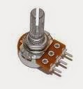
- Relay (with coil rating with 6VDC Or 5VDC)
- Connecting wires/Jumper wires.
- PC to configure arduino board (with arduino software installed).
- Bread board.


Explanation to Circuit :
As we have to control external circuit or element through relay first of all we have to consider the relay structure its working principle and how to operate it for automation of things.
.jpg)

Here i have posted two pictures of most commonly used DC relays after applying 5VDC to its coil terminals the relay coil will get energized and the movable pin will get connected with NO point and after releasing the voltage the movable pin will gets to its start position with NC pin so this is the key principle to remember while working with relays of any kind.
The circuit we have shown is used to operate the relay with Arduino board directly by applying 5Vdc and Gound to jack1 and middle pin will goto the transistor base pin which will amplify the arduino Current of 50ma max to 200ma round about and which will be enough to energize the relay coil. The led1 will only indicate the ON and OFF the state of relay and can be omitted.
Steps to follow :
- Connect the Circuit according to schematic image on bread board.
- Plud the Middle pin of jack1 to arduino pin 5.
- Connect the 5v and groung connections correctly.
- Use Qn3904 or D400 transister (Recommended and tested).
- Check polaroty of Transister before applying to any Circuit.
- The resisters and LED part of circuit is not much essential so you can ignore it the circuit will still work better.
- Connect JP2 pin 2 relay on arduino PIN 13 of LED and power it up with 5v and ground.
- open up the Arduino IDE in PC and upload the following code.
- After succesfull u[loading you can control the devices with your tv remote.
- Whatever switch which you want to get controlled you can connect it to relay outputs. or at JP3 connector.
Code to be uploaded :
#include <IRremote.h>
#define irPin 3
IRrecv irrecv(irPin);
decode_results results;
int vcc = 12;
int gnd = 11;
int in = 10 ;
int led = 13;
int light = 4;
void setup() {
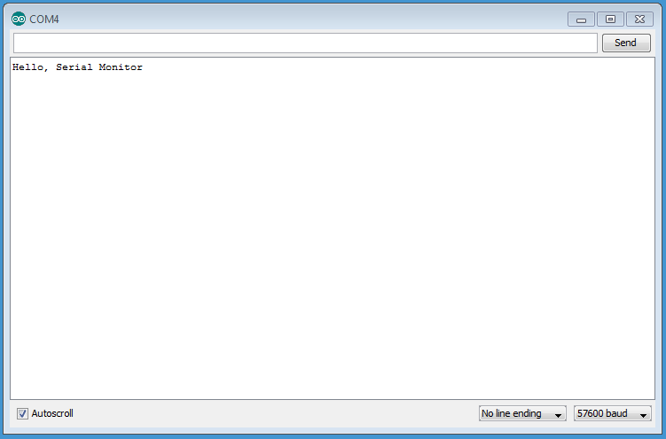
Serial.begin(9600);
pinMode(vcc,OUTPUT);
pinMode(led,OUTPUT);
pinMode(gnd,OUTPUT);
pinMode(in,INPUT);
digitalWrite(vcc, HIGH);
digitalWrite(gnd, LOW);
digitalWrite(led, LOW);
digitalWrite(light, LOW);//
irrecv.enableIRIn();
}
void loop() {
if (irrecv.decode(&results)) {
switch (results.value) {
case 0xFF30CF:
Serial.println("1");
break;
case 0xFF18E7:
Serial.println("2");
break;
case 0xFF7A85:
//Serial.println("POWER");
if(digitalRead(13)==HIGH)
{
digitalWrite(led, LOW);// turn on the led on pin 13
digitalWrite(light, LOW);//
Serial.println("LED Turned OFF");
}
else if(digitalRead(13)==LOW)
{
digitalWrite(led, HIGH);// turns off the led at pin 13
digitalWrite(light, HIGH);//
Serial.println("LED Turned ON");
}
break;
}
irrecv.resume();
}
}
If you have any more things to ask let it be in comments i will try to more explain it.